How precise can I get Arduino using rotary encoders?
Using a rotary encoder on an Arduino
- Overview. A rotary encoder is a sensor used for determining the angular position of a shaft, similar to a potentiometer.
- Understanding a Rotary Encoder. A rota r y encoder can essentially be used for the same purpose as the potentiometer. ...
- Connecting it to an Arduino. ...
- Demo + How to Code. ...
How to build a rotary encoder circuit with an Arduino?
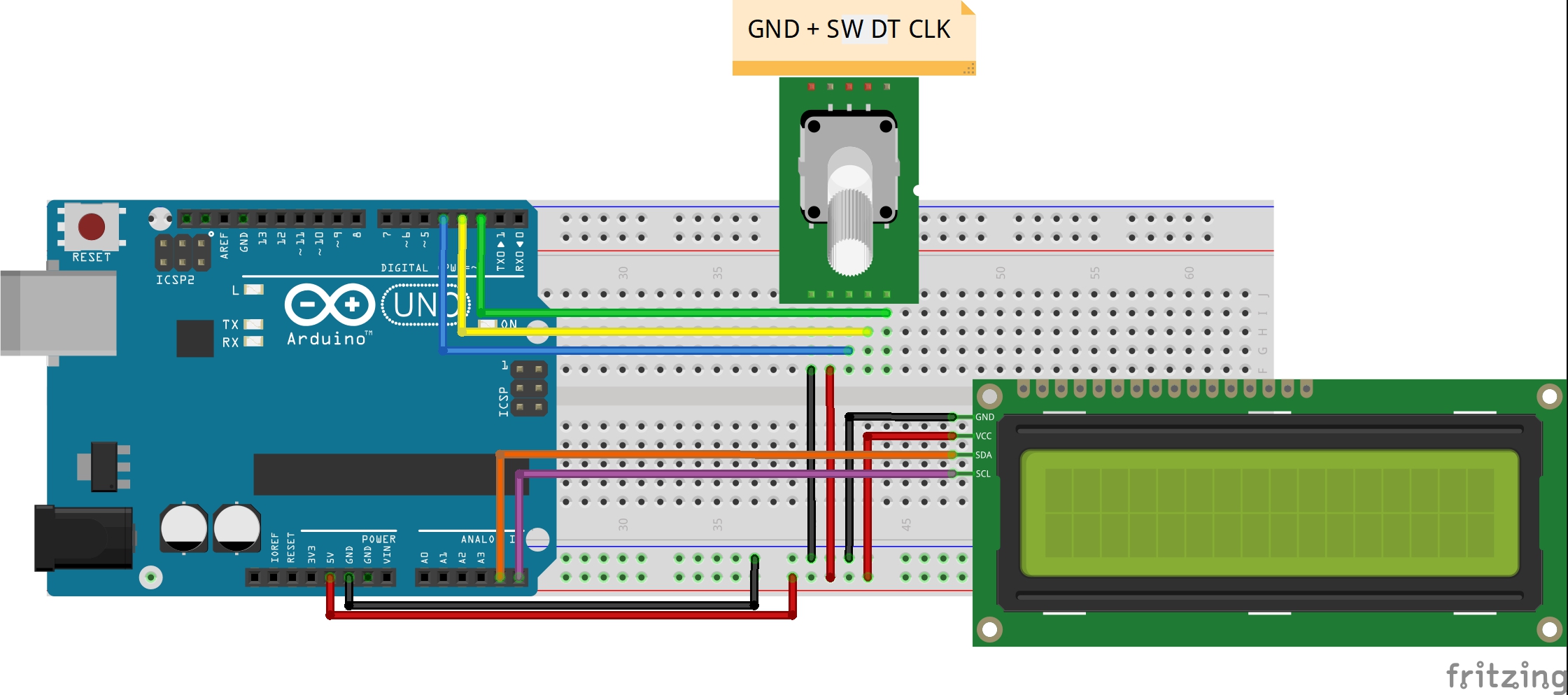
Rotary Encoder Arduino Interface. Connect the power supply pins of Rotary Encoder to Arduino board as + to 5V and Gnd to Gnd. Then connect CLK (Encoder out A) Pin to Arduino digital Pin D2 and DT (Encoder out B) pin to digital pin D1. After completing the hookup upload the following Sketch to get the angle and position of rotary encoder in ...
What is the purpose of a rotary encoder?
Rotary encoders deliver pulses, which you count, to get position feedback from the motion system. I have only used them on PLC-controlled systems for position feedback and machine timing, never with a stepper motor, but it essentially works like this: Condition is met to pulse motor to a certain point.
How to use a rotary encoder?
What You Will Learn
- What the rotary encoder is and how it works.
- Displaying encoder position
- Controlling a LED light using a rotary encoder
- Controlling a DC motor speed and direction using a rotary encoder
How do I use a rotary encoder with Arduino?
Wiring – Connecting Rotary Encoder to Arduino Connections are fairly simple. Start by connecting +V pin on the module to 5V on the Arduino and GND pin to ground. Now connect the CLK and DT pins to digital pin#2 and #3 respectively. Finally, connect the SW pin to a digital pin #4.
What is an Arduino rotary encoder?
A rotary encoder is a position sensor used to determine the angular position of a rotating shaft. It can be used with an Arduino through modules to achieve such functionality.
How do I connect rotary encoder to Arduino Nano?
Arduino Nano: Rotary Encoder With VisuinoStep 1: Components. ... Step 2: Connect the Rotary Encoder to Arduino. ... Step 3: Start Visuino, and Select the Arduino Board Type. ... Step 4: In Visuino: Add and Connect Rotary Encoder Component. ... Step 5: In Visuino: Add and Connect Up/Down Counter Component.More items...
What do you use a rotary encoder for?
Rotary encoders are used to control the speed of the conveyer belt as well as the direction of the movement. They are required in warehouse distribution systems, baggage handling systems and case-packing systems.
How do you use the rotary encoder button?
1:001:39Rotary encoder with push-button on Arduino - YouTubeYouTubeStart of suggested clipEnd of suggested clipClick double click hold. And release after hold for example I use this encoder to navigate myMoreClick double click hold. And release after hold for example I use this encoder to navigate my cycling machine parameters click to move forward double click to go back digit rotate.
How do you use a 3 pin rotary encoder?
2:314:54How Rotary Encoder Works and How To Use It with Arduino - YouTubeYouTubeStart of suggested clipEnd of suggested clipThe first pin is the output pin a the second pin is the output pin b the third pin is the button pinMoreThe first pin is the output pin a the second pin is the output pin b the third pin is the button pin and of course the two other pins are the vcc and the ground pin.
How do you test a rotary encoder?
0:212:02Testing the Encoder Sensor - YouTubeYouTubeStart of suggested clipEnd of suggested clipB next connect the tester's positive lead to pin c. And then connect tester's negative lead to pin bMoreB next connect the tester's positive lead to pin c. And then connect tester's negative lead to pin b. While very slowly rotating the shaft on the encoder.
What is a rotary encoder module?
The Rotary Encoder Module is a continuously variable position sensor that reports the relative position of the shaft, the direction of rotation and if the shaft is depressed.
What is the purpose of the CLK pin in the rotary encoder?
3. What is the purpose of the CLK pin in the rotary encoder? Explanation: The rotary encoder has a CLK pin and a DATA pin. The DATA pin gives out pulses which vary in phase depending upon the direction of rotation of the rotary encoder.
What is the output of rotary encoder?
Rotary encoders provide a position feedback signal of a rotating shaft or object. They are available with analog (0-5V, 0-10V or 4-20mA) or digital output (incremental quadrature, CAN or DeviceNET) and protection grade up to NEMA 6 or IP68.
How many pins does a rotary encoder have?
Rotary Encoder Arduino Example The particular module that I will use for this example comes on a breakout board and it has five pins.
How do I read an incremental encoder in Arduino?
0:3710:32Reading an Incremental Encoder Using an Arduino - YouTubeYouTubeStart of suggested clipEnd of suggested clipAnd the phase between them or which one is going first which one is leading tells you the directionMoreAnd the phase between them or which one is going first which one is leading tells you the direction of a rotation. So if you've never. Looked at encoder signals on an oscilloscope.
Step 1: Preparation
If you haven’t yet, please see my other Instructable on rotary encoder reading to find out how to set up your hardware and Arduino IDE software.
Step 2: Code
This is the code. By looking at the structure and the comments I hope you will find it easy to adapt for your specific needs!
Step 3: Operation and Conclusion
If you open the serial monitor in Arduino after uploading this sketch, and start to turn the encoder shaft, you should see the top level menu rotating through the number of sub-menus/options you have (limited using the modeMax variable).
What is a rotary encoder?
Rotary Encoders are used in several systems where precision and feedback in terms of rotational motion or angular position are required. By turning the shaft to the right or left, we either get an increase or decrease in value (depending on the configuration).
What are the remaining pieces of code in a loop?
The remaining pieces of code are the functions used within the loop including the drawmenu () function and the function to read the rotary encoder.
What is void loop?
Up next is the void loop () function. This function is the most complex part of the whole code. The function basically creates the menu and uses the variables created initially to keep track of the previous, current and next state so when the rotary encoder is turned, it knows the right menu to display. The menu selection part of the code is also handled by a routine within the void loop () function.
Is the code for the tutorial more complex than the last tutorial?
The code for this version of the tutorial is a little bit more complex compared to that of the last tutorial and you may need to replicate it yourself before you really understand the full scope of it.
Is rotary encoder analog or digital?
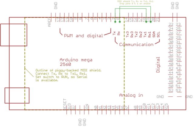
Schematics. The rotary encoder used is an analog device, and for that reason all its three output pins are connected to analog pins on the Arduino. To make the connections easier to follow, a pin map between the components is provided below.
What is rotary encoder?
Rotary encoder is an electronic component capable of monitoring movement and position when rotating. Rotary encoder utilizes optical sensors that can generate pulses when the rotary encoder rotates. Application of the rotary encoder usually as a mechanical or robotic motion monitor can also be used for menu selection on the display.
What does 1 mean on a rotary?
1 = the start button value of the rotary when it has not been pressed
What pins are used to connect to the interrupt foot?
One of the DT or CLK pins must be connected to the interrupt foot of Arduino Uno, or both of the DT and CLK are connected to the interrupt pin.
How to find valrotary value?
ValRotary value is the value of the number of steps that have been running. ValRotary value is obtained from rotary sensor encoder reading value divided by 2.5. A value of 2.5 is obtained from the test, since one step of the rotary encoder may exceed 1, so divide by 2.5 for its value according to the perstep and also the addition of the read delay.#N#While on line 19 - 25 is a program to determine whether rotary rotary encoder CW or CCW. The explanation of lines 19 - 25 is when the current rotary encoder readout is greater than the previous rotary data then expressed as CW. Whereas if the current reading is smaller than the previous reading then it is stated as CCW.
multiple encoders
Try out http://code.google.com/p/adaencoder/ and PinChangeInt library ( http://code.google.com/p/arduino-pinchangeint/) see...
Raspberry Pi menu for rotary encoder
When using the Raspberry Pi as the menu display system we need to do a few things to a stock raspbian install...
